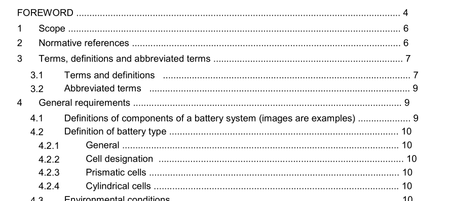
IEC 62973-4-2021 pdf Railway applications – Rolling stock – Batteries for auxiliary power supply systems – Part 4: Secondary sealed nickel-metal hydride batteries

4.2 Definition of battery type General 4.2.1 A battery consists of a number of cells or battery modules and/or assembled in trays, crates, and then assembled in a battery box. A cell consists of positive and negative plates, electrolyte, metal container and sealing cap. Positive and negative terminals, which are apart by a separator, are housed and sealed in the metal container with a sealing cap. The sealing cap consists of a positive terminal, a pressure release valve and an insulator which are insulated to a negative part that forms a container. The container wears an insulating envelope. The positive active material is nickel hydroxide, and the negative active material is hydrogen absorbed nickel-alloy. The electrodes are surrounded by electrolyte, an aqueous solution mainly of potassium hydroxide (KOH), and distilled or deionized water. The electrolyte does not chemically change or degrade due to charge/discharge cycles.
The interface system between the battery charging system and the battery box as shown in Figure 4 consists of: a) Battery voltage sensing and regulation; maximum ±1 % tolerance (see (1) in Figure 4); b) Temperature data acquisition, (2a), including wiring (2b) to the sensor (3); typically, better than ±2,5 K tolerance; c) Temperature sensor (3): maximum tolerance ±2 K for the specified temperature range preferably attached to the battery, minimum one sensor per battery system (see (3)); The choice of the temperature sensor shall be agreed between the system integrator and the suppliers of the battery and battery charging system; d) Position of the temperature sensor (3) within the battery box (4); e) Cabling between battery and battery charger; part of system integration in the rolling stock (5). The system integrator will check if and how the effect of the wiring needs to be compensated, considering voltage drop in the power cables and resistance in the temperature sensor wires. The impact of the sensor wiring depends on the type of temperature sensor, data acquisition system and/or location of the voltage sensor. If there are significant influences, it is possible to compensate these influences in the battery charger control system upon agreement between the system integrator and the manufacturer of the battery charging system. With the recommended temperature sensors, the influence of the wiring resistance on the temperature acquisition can be neglected.
- Previous:IEC 62975-2021 pdf Natural esters – Guidelines for maintenance and use in electrical equipment
- Next:IEC 62830-5-2021 pdf Semiconductor devices – Semiconductor devices for energy harvesting and generation – Part 5: Test method for measuring generated power from flexible thermoelectric devices
- ISO IEC 27050-4-2021 pdf Information technology — Electronic discovery — Part 4: Technical readiness
- ISO IEC 27036-1-2021 pdf Cybersecurity — Supplier relationships — Part 1: Overview and concepts
- ISO IEC 27013-2021 pdf Information security, cybersecurity and privacy protection — Guidance on the integrated implementation of ISO/IEC 27001 and ISO/IEC 20000-1
- ISO IEC 26580-2021 pdf Software and systems engineering — Methods and tools for the feature- based approach to software and systems product line engineering
- ISO IEC 24735-2021 pdf Information technology — Office equipment — Method for measuring digital copying productivity
- ISO IEC 24711-2021 pdf Information technology — Office equipment — Method for the determination of ink cartridge yield for colour inkjet printers and multi- function devices that contain printer components
- ISO IEC 23544-2021 pdf Information Technology — Data centres — Application Platform Energy Effectiveness (APEE)
- ISO IEC 23510-2021 pdf Information technology — 3D printing and scanning — Framework for an Additive Manufacturing Service Platform (AMSP)
- ISO IEC 23127-1-2021 pdf Information technology — Learning, education, and training — Metadata for facilitators of online learning — Part 1: Framework
- ISO IEC 23126-2021 pdf Information technology for learning, education and training — Ubiquitous learning resource organization and description framework
- IEC 60243-2-2013 pdf Electric strength of insulating materials – Test methods – Part 2: Additional requirements for tests using direct voltage
- IEC 60317-37-2013 pdf Specifications for particular types of winding wires – Part 37: Polyesterimide enamelled round copper wire, class 180, with a bonding layer
- IEC 60317-31-2015 pdf Specifications for particular types of winding wires – Part 31: Glass fibre wound, resin or varnish impregnated, bare or enamelled rectangular copper wire, temperature index 180
- IEC TS 63297-2021 pdf Sensing devices for non-intrusive load monitoring , NILM ) systems
- IEC 61215-1-2-2021 pdf Terrestrial photovoltaic (PV) modules – Design qualification and type approval – Part 1-2: Special requirements for testing of thin-film Cadmium Telluride (CdTe) based photovoltaic (PV) modules
- BS ISO IEC 15420-2009 pdf Information technology一 Automatic identification and data capture techniques EAN/UPC bar code symbology specification
- BS ISO IEC 19762.5-2008 pdf Information technology一 Automatic identification and data capture (AIDC) techniques – Harmonized vocabulary Part 5: Locating systems
- BS IEC 60860-2014 pdf Radiation protection instrumentation一 Warning equipment for criticality accidents
- ISO IEC 24735-2021 pdf Information technology — Office equipment — Method for measuring digital copying productivity
- ISO IEC 24711-2021 pdf Information technology — Office equipment — Method for the determination of ink cartridge yield for colour inkjet printers and multi- function devices that contain printer components