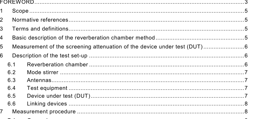
IEC 61726-2015 pdf Cable assemblies, cables, connectors and passive microwave components – Screening attenuation measurement by the reverberation chamber method

For the determination of the screening attenuation, the tracking generator output has to be connected to the DUT instead of the input antenna and the measurement sequence from the first step is repeated. Then the screening attenuation simply can be calculated by subtracting the result from the first step from the one of the second step. This can either be done in a post processing step as well as by using the thru-calibration of modern spectrum analysers with build in tracking generators (therefore the first step is used to calibrate the system). To check the maximum dynamic range, the DUT needs to be replaced by a shielded match load and the second measurement has to be performed with this configuration. If the result is not fulfilling the needs on dynamic range, the resolution bandwidth hast to be reduced. It has to be kept in mind that this might enlarge the measurement time a lot because a reduced measurement bandwidth is coming along with an enlarged sweep time. 7.3 Measurement of the insertion loss of the cavity The synthesized generator is connected to the input antenna and set to deliver a constant power at a fixed frequency. The mode stirrer is also set to rotate at a constant speed. All parameters, i.e. rotation speed and spectrum analyzer set-up (except for input attenuator and reference level) shall be the same as those used during DUT measurement. The spectrum analyser is connected to the output of the reference antenna. After a complete revolution of the mode stirrer, the maximum value of the power is recorded.
7.4.3 Measurement of a calibrator A calibrator is a device having stable screening attenuation. An example of a calibrator is given in Annex B. Such a calibrator should be measured during the full calibration procedure for the test set-up, and compared to previous measurements. This enables the detection of any deviations or malfunctioning of the test set-up. The calibrator is the subject of on-going study to derive its theoretical screening attenuation from Z t and Z f , in order to provide the necessary data for calibration of the test equipment. 7.4.4 Measurement of lossy DUT Some inaccuracy may occur when measuring a lossy DUT, due to insufficient moding of the reverberation chamber. This may be checked by verifying that during one revolution of the mode stirrer, the ratio between the maximum and the minimum power at the output of the reference antenna exceeds 20 dB.
- ISO IEC 27050-4-2021 pdf Information technology — Electronic discovery — Part 4: Technical readiness
- ISO IEC 27036-1-2021 pdf Cybersecurity — Supplier relationships — Part 1: Overview and concepts
- ISO IEC 27013-2021 pdf Information security, cybersecurity and privacy protection — Guidance on the integrated implementation of ISO/IEC 27001 and ISO/IEC 20000-1
- ISO IEC 26580-2021 pdf Software and systems engineering — Methods and tools for the feature- based approach to software and systems product line engineering
- ISO IEC 24735-2021 pdf Information technology — Office equipment — Method for measuring digital copying productivity
- ISO IEC 24711-2021 pdf Information technology — Office equipment — Method for the determination of ink cartridge yield for colour inkjet printers and multi- function devices that contain printer components
- ISO IEC 23544-2021 pdf Information Technology — Data centres — Application Platform Energy Effectiveness (APEE)
- ISO IEC 23510-2021 pdf Information technology — 3D printing and scanning — Framework for an Additive Manufacturing Service Platform (AMSP)
- ISO IEC 23127-1-2021 pdf Information technology — Learning, education, and training — Metadata for facilitators of online learning — Part 1: Framework
- ISO IEC 23126-2021 pdf Information technology for learning, education and training — Ubiquitous learning resource organization and description framework
- IEC 60974-11-2021 pdf Arc welding equipment – Part 11: Electrode holders
- IEC TR 63274-2021 pdf Power consumption of high dynamic range television sets
- DD IEC TS 62257-9-3-2007 pdf Recommendations for small renewable energy and hybrid systems for rural electrification- Part 9-3: Integrated system – User interface
- IEC 62875-2015 pdf Multimedia systems and equipment – Multimedia e-publishing and e-book technologies – Printing specification of texture map for auditory presentation of printed texts
- AS IEC 60433-2007 pdf Insulators for overhead lines with a nominal voltage above 1000 V- Ceramic insulators for a.c. systems- Characteristics of insulator units of the long rod type
- BS ISO IEC 15420-2009 pdf Information technology一 Automatic identification and data capture techniques EAN/UPC bar code symbology specification
- BS ISO IEC 19762.5-2008 pdf Information technology一 Automatic identification and data capture (AIDC) techniques – Harmonized vocabulary Part 5: Locating systems
- BS IEC 60860-2014 pdf Radiation protection instrumentation一 Warning equipment for criticality accidents
- ISO IEC 24735-2021 pdf Information technology — Office equipment — Method for measuring digital copying productivity
- ISO IEC 24711-2021 pdf Information technology — Office equipment — Method for the determination of ink cartridge yield for colour inkjet printers and multi- function devices that contain printer components