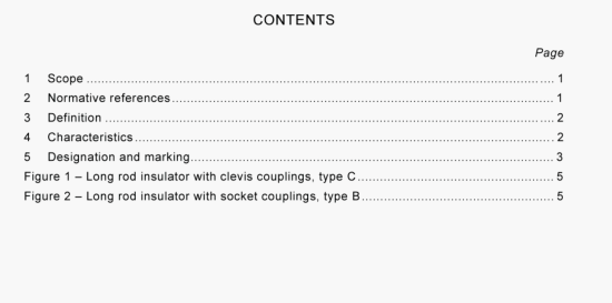
AS IEC 60433-2007 pdf Insulators for overhead lines with a nominal voltage above 1000 V- Ceramic insulators for a.c. systems- Characteristics of insulator units of the long rod type

For the purposes of this International Standard, the following definition applies:
The corresponding values are specified in table 1. The minimum nominal creepage distances are based on a specific creepage distance of 16 mm/kV for the lowest value of the highest voltage for equipment corresponding to the specifed value of the standard lightning impulse withstand (in accordance with IEC 60071-1).
NOTES
1 The tolerances given in IEC 60383-1 are applicable to all the dimensions in table 1, even it the adjectives “minimum” or “maximum” are used before the term “nominal”.
2 Dry lightning impulse withstand vollage and wet power frequency withstand voltage are specifhed in table 1 for single unit string insulators. values of withstand voltages of insulator strings consisting of more than one unit are not contained in this standard.
3 The rod diameter is not specilied since it depends on the mechanical characteristics of the insulating material. Information on the definition and classification of ceramic insulating materials can be found in IEC 60672-1 and IEC 60672-3.
Long rod insulators are designated in table 1 by letter L, followed by a figure indicating the specified mechanical falling load in kilonewtons. Then follows the letters B or C indicating ball and socket or clevis and tongue coupling respectively, followed by the value of the lightning impulse withstand voltage in kilovolts.
The insulators shall be marked either on the upper shed or on the metal parts with the name or trade mark of the manufacturer and the year of manufacture. In addition, each unit shall be marked with the specified mechanical failing load, by using the first part of the designation; for instance, the insulator shall be marked L 160 for the units with 160 kN specified mechanical failing load.
These markings shall be legible and indelible.
Figure 1 shows a long rod insulator with clevis couplings, figure 2 shows a long rod insulator with socket couplings.
- ISO IEC 27050-4-2021 pdf Information technology — Electronic discovery — Part 4: Technical readiness
- ISO IEC 27036-1-2021 pdf Cybersecurity — Supplier relationships — Part 1: Overview and concepts
- ISO IEC 27013-2021 pdf Information security, cybersecurity and privacy protection — Guidance on the integrated implementation of ISO/IEC 27001 and ISO/IEC 20000-1
- ISO IEC 26580-2021 pdf Software and systems engineering — Methods and tools for the feature- based approach to software and systems product line engineering
- ISO IEC 24735-2021 pdf Information technology — Office equipment — Method for measuring digital copying productivity
- ISO IEC 24711-2021 pdf Information technology — Office equipment — Method for the determination of ink cartridge yield for colour inkjet printers and multi- function devices that contain printer components
- ISO IEC 23544-2021 pdf Information Technology — Data centres — Application Platform Energy Effectiveness (APEE)
- ISO IEC 23510-2021 pdf Information technology — 3D printing and scanning — Framework for an Additive Manufacturing Service Platform (AMSP)
- ISO IEC 23127-1-2021 pdf Information technology — Learning, education, and training — Metadata for facilitators of online learning — Part 1: Framework
- ISO IEC 23126-2021 pdf Information technology for learning, education and training — Ubiquitous learning resource organization and description framework
- IEC 60502-1-2021 pdf Power cables with extruded insulation and their accessories for rated voltages from 1 kV (U m = 1,2 kV) up to 30 kV (U m = 36 kV) – Part 1: Cables for rated voltages of 1 kV (U m = 1,2 kV) and 3 kV (U m = 3,6 kV)
- IEC 62340-2007 pdf Nuclear power plants – Instrumentation and control systems important to safety – Requirements for coping with common cause failure (CCF)
- IEC 62845-2015 pdf Railway applications – Radio remote control system of traction vehicles for shunting application
- IEC 60794-1-403-2021 pdf Optical fibre cables – Part 1-403: Generic specification – Basic optical cable test procedures – Electrical test methods – Electrical continuity test of cable metallic elements, method H3
- BS IEC 62843-2013 pdf Standard for N times 64 kilobit per second optical fiber interfaces between teleprotection and multiplexer equipment
- BS ISO IEC 15420-2009 pdf Information technology一 Automatic identification and data capture techniques EAN/UPC bar code symbology specification
- BS ISO IEC 19762.5-2008 pdf Information technology一 Automatic identification and data capture (AIDC) techniques – Harmonized vocabulary Part 5: Locating systems
- BS IEC 60860-2014 pdf Radiation protection instrumentation一 Warning equipment for criticality accidents
- ISO IEC 24735-2021 pdf Information technology — Office equipment — Method for measuring digital copying productivity
- ISO IEC 24711-2021 pdf Information technology — Office equipment — Method for the determination of ink cartridge yield for colour inkjet printers and multi- function devices that contain printer components