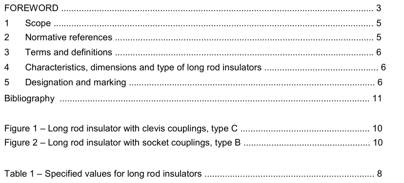
IEC 60433-2021 pdf Insulators for overhead lines with a nominal voltage above 1 000 V – Ceramic insulators for AC systems – Characteristics of insulator units of the long rod type

3 Terms and definitions For the purposes of this document, the following terms and definitions apply. ISO and IEC maintain terminological databases for use in standardization at the following addresses: • • IEC Electropedia: available at http://www.electropedia.org/ ISO Online browsing platform: available at http://www.iso.org/obp 3.1 long rod insulator suspension or tension insulator consisting of an approximately cylindrical insulating part provided with sheds and equipped at the ends with external metal fittings Note 1 to entry: The insulator is designed in such a manner that the shortest puncture path through solid insulating material is at least equal to half the arcing distance. Therefore it is a class A insulator according to IEC 60383-1. 4 Characteristics, dimensions and type of long rod insulators String insulator units of the long rod type are characterised by the following specified characteristics: – the standard lightning impulse withstand voltage (see IEC 60071 -1); – the wet power frequency withstand voltage (see IEC 60071 -1); – the tensile mechanical failing load; – the maximum nominal length L of the insulator; – the maximum nominal diameter D of the insulating part; – the minimum nominal creepage distance; – the standard coupling. The corresponding values are specified in Table 1. The minimum nominal creepage distances are based on a unified specific creepage distance of 27,8 mm/kV for the lowest value of the highest voltage for equipment corresponding to the specified value of the standard lightning impulse withstand (in accordance with IEC 60071 -1). NOTE 1 The tolerances given in IEC 60383-1 are applicable to all the dimensions in Table 1, even if the adjectives “minimum” or “maximum” are used before the term “nominal”. NOTE 2 Dry lightning impulse withstand voltage and wet power frequency withstand voltage are specified in Table 1 for single unit string insulators.
The insulators shall be marked either on the upper shed or on the metal parts with the name or trade mark of the manufacturer and the year of manufacture. In addition, each unit shall be marked with the specified mechanical failing load, by using the first part of the designation; for instance, the insulator shall be marked L 160 for the units with 160 kN specified mechanical failing load. These markings shall be legible and indelible. Figure 1 shows a long rod insulator with clevis couplings. Figure 2 shows a long rod insulator with socket couplings.
- Previous:IEC 60502-1-2021 pdf Power cables with extruded insulation and their accessories for rated voltages from 1 kV (U m = 1,2 kV) up to 30 kV (U m = 36 kV) – Part 1: Cables for rated voltages of 1 kV (U m = 1,2 kV) and 3 kV (U m = 3,6 kV)
- Next:IEC 60305-2021 pdf Insulators for overhead lines with a nominal voltage above 1 000 V – Ceramic or glass insulator units for AC systems – Characteristics of insulator units of the cap and pin type
- ISO IEC 27050-4-2021 pdf Information technology — Electronic discovery — Part 4: Technical readiness
- ISO IEC 27036-1-2021 pdf Cybersecurity — Supplier relationships — Part 1: Overview and concepts
- ISO IEC 27013-2021 pdf Information security, cybersecurity and privacy protection — Guidance on the integrated implementation of ISO/IEC 27001 and ISO/IEC 20000-1
- ISO IEC 26580-2021 pdf Software and systems engineering — Methods and tools for the feature- based approach to software and systems product line engineering
- ISO IEC 24735-2021 pdf Information technology — Office equipment — Method for measuring digital copying productivity
- ISO IEC 24711-2021 pdf Information technology — Office equipment — Method for the determination of ink cartridge yield for colour inkjet printers and multi- function devices that contain printer components
- ISO IEC 23544-2021 pdf Information Technology — Data centres — Application Platform Energy Effectiveness (APEE)
- ISO IEC 23510-2021 pdf Information technology — 3D printing and scanning — Framework for an Additive Manufacturing Service Platform (AMSP)
- ISO IEC 23127-1-2021 pdf Information technology — Learning, education, and training — Metadata for facilitators of online learning — Part 1: Framework
- ISO IEC 23126-2021 pdf Information technology for learning, education and training — Ubiquitous learning resource organization and description framework
- IEC TR 63042-303-2021 pdf UHV AC transmission systems – Part 303: Guideline for the measurement of UHV AC transmission line power frequency parameters
- IEC 61472-2-2021 pdf Live working – Minimum approach distances – Part 2: Method of determination of the electrical component distance for AC systems from 1,0 kV to 72,5 kV
- IEC 60860-2014 pdf Radiation protection instrumentation – Warning equipment for criticality accidents
- IEC 61188-6-2-2021 pdf Circuit boards and circuit board assemblies – Design and use – Part 6-2: Land pattern design – Description of land pattern for the most common surface mounted components (SMD)
- IEC 61468-2021 pdf Nuclear power plants – Instrumentation systems important to safety – In-core instrumentation: Characteristics and test methods of self-powered neutron detectors
- BS ISO IEC 15420-2009 pdf Information technology一 Automatic identification and data capture techniques EAN/UPC bar code symbology specification
- BS ISO IEC 19762.5-2008 pdf Information technology一 Automatic identification and data capture (AIDC) techniques – Harmonized vocabulary Part 5: Locating systems
- BS IEC 60860-2014 pdf Radiation protection instrumentation一 Warning equipment for criticality accidents
- ISO IEC 24735-2021 pdf Information technology — Office equipment — Method for measuring digital copying productivity
- ISO IEC 24711-2021 pdf Information technology — Office equipment — Method for the determination of ink cartridge yield for colour inkjet printers and multi- function devices that contain printer components