DD IEC TS 62257-9-4-2007 pdf Recommendations for small renewable energy and hybrid systems for rural electrification – Part 9-4: Integrated system – – User installation

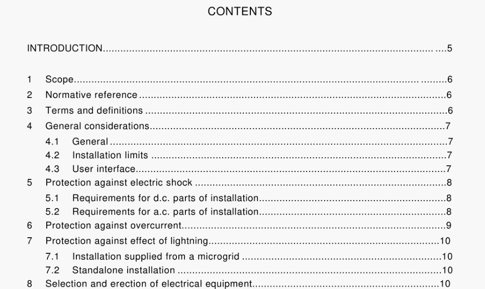
7 Protection against effect of lightning 7.1 Installation supplied from a microgrid The overvoltage protection, where necessary, is provided on the microgrid side. 7.2 Standalone installation If the distance between the external generator and the user’s installation is less than 15 m: no special measure is required. If the distance between the external generator and the user’s installation is greater than 15 m and the number of thunderstorm days per year (obtained from iso-keraunic maps) is high (generally more than 25 days per year), a conductor made of bare copper with a sectional area of at least 10 mm2 shall be installed between the external generator and the user’s installation. It shall be installed in the same ditch as the electrical cable (laid in a conduit) as close as possible to it. This creates an equipotential bonding system as shown in Figure 3. One of the ends shall be connected to the earthing electrode of the external generator and the other shall be connected to a special terminal provided for this purpose at the user’s installation. SPDs shall be installed between the two polarities and between each polarity and the earth at the two ends of the bonding conductor. For specific requirements for generators, refer to the appropriate parts of the IEC 62257-7 series.
8 Selection and erection of electrical equipment 8.1 Wiring system 8.1.1 General The number of subcircuits shall be determined according to the position of the consumption points, their nature and the foreseeable load. Separate neutral and protective conductors shall be provided for each subcircuit. The cross-sectional area of conductors is chosen to provide for a satisfactory lifetime of conductors and insulation subjected to the thermal effects of carrying current for prolonged periods of time in normal service (See tables in IEC 60364-5-52). Other considerations that affect the choice of cross . sectional area of conductors are: ●to fulfill maximum acceptable voltage drop, to withstand the electro-dynamic stresses which can occur in the event of a short-circuit, ●to withstand the other mechanical stresses to which the conductors may be subjected, to ensure an impedance value compatible with operation of the short-circuit protection devices. 8.1.2 Voltage drops The maximum voltage drops in the installation shall not be greater than those indicated in Table 2.
- Previous:IEC 60034-5-2006 pdf Rotating electrical machines - Part 5: Degrees of protection provided by the integral design of rotating electrical machines (IP code) - . Classification
- Next:DD IEC TS 62257-9-3-2007 pdf Recommendations for small renewable energy and hybrid systems for rural electrification- Part 9-3: Integrated system - User interface
- ISO IEC 27050-4-2021 pdf Information technology — Electronic discovery — Part 4: Technical readiness
- ISO IEC 27036-1-2021 pdf Cybersecurity — Supplier relationships — Part 1: Overview and concepts
- ISO IEC 27013-2021 pdf Information security, cybersecurity and privacy protection — Guidance on the integrated implementation of ISO/IEC 27001 and ISO/IEC 20000-1
- ISO IEC 26580-2021 pdf Software and systems engineering — Methods and tools for the feature- based approach to software and systems product line engineering
- ISO IEC 24735-2021 pdf Information technology — Office equipment — Method for measuring digital copying productivity
- ISO IEC 24711-2021 pdf Information technology — Office equipment — Method for the determination of ink cartridge yield for colour inkjet printers and multi- function devices that contain printer components
- ISO IEC 23544-2021 pdf Information Technology — Data centres — Application Platform Energy Effectiveness (APEE)
- ISO IEC 23510-2021 pdf Information technology — 3D printing and scanning — Framework for an Additive Manufacturing Service Platform (AMSP)
- ISO IEC 23127-1-2021 pdf Information technology — Learning, education, and training — Metadata for facilitators of online learning — Part 1: Framework
- ISO IEC 23126-2021 pdf Information technology for learning, education and training — Ubiquitous learning resource organization and description framework
- IEC TR 63250-2021 pdf Household and similar electrical appliances – Method of measuring performance – Assessment of repeatability, reproducibility and uncertainty
- IEC TS 63297-2021 pdf Sensing devices for non-intrusive load monitoring , NILM ) systems
- IEC 61453-2007 pdf Nuclear instrumentation – Scintillation gamma ray detector systems for the assay of radionuclides – Calibration and routine tests
- IEC 62858-2015 pdf Lightning density based on lightning location systems (LLS) – General principles
- IEC 60836-2015 pdf Specifications for unused silicone insulating liquids for electrotechnical purposes
- BS ISO IEC 15420-2009 pdf Information technology一 Automatic identification and data capture techniques EAN/UPC bar code symbology specification
- BS ISO IEC 19762.5-2008 pdf Information technology一 Automatic identification and data capture (AIDC) techniques – Harmonized vocabulary Part 5: Locating systems
- BS IEC 60860-2014 pdf Radiation protection instrumentation一 Warning equipment for criticality accidents
- ISO IEC 24735-2021 pdf Information technology — Office equipment — Method for measuring digital copying productivity
- ISO IEC 24711-2021 pdf Information technology — Office equipment — Method for the determination of ink cartridge yield for colour inkjet printers and multi- function devices that contain printer components