AS IEC 60720-2007 pdf Characteristics of line post insulators (IEC 60720, Ed. 1.0 (1981) MOD)

Each line post insulator is characterized by the specified minimum bending failing load. Generally, this bending failing load is 12.5 kN; in addition, for tie-top line insulators of impulse withstand voltage levels up to and including 170 kV, itis 8 kN. The bending load is applied at the centre of the side groove in the case of a tie-top type insulator and at the point determined by dimension H in the case of a clamp-top type insulator.
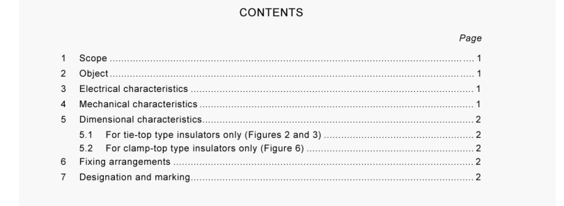
2 Object The object of this standard is to prescribe specified values for electrical and mechanical characteristics and for the principal dimensions of line insulators of ceramic material (see Tables I and I). NOTE – General definitions and methods of tests are given in IEC 60383. Tosts on insulators of ceramic material or gla8s for overhead lines with日nominat voltage greater than 1000 V. AS/NZS 2917.1, Insulators Porcelain and glass for overhead power lines- Voltages greater than 1000 a.c. Part 1: Test methods- Insulator units
5.1 For tie-top type insulators only (Figures 2 and 3) Head diameter. Neck diameter. Top groove radius. Side groove radius. Distance between bottom of top groove and centre line of side groove. NOTE – By agreement between the purchaser and the manufacturer, the insulator may be manufactured without top groove. It is also possible, by agreement, to use the head of Figure 3 for types R 200, R 250 and R 325. 5.2 For clamp-top type insulators only (Figure 6) Dimensions of clamp-top bracket.
6 Fixing arrangements The fixing arrangements shall be in accordance with Figure 8. The centre hole diameters shall have Iso metric threads and may be oversize by not more than 0.25 mm (0.01 in). They shall be suitable for steel pins having standard threads after galvanizing.
7 Designation and marking Line post insulators are designated in Tables I and II by the letter R following by figures indicating the bending failing load in kilonewtons. Then follows the letter E or J indicating external or internal fixing of the metal parts. This is followed by the letter T, C or H indicating tie-top type, vertical mounting clamp-top type or horizontal mounting clamp-top type, respectively. The following figure indicates the specified lightning impulse withstand voltage in kilovolts. The letter N or L which then follows, indicates normal or longer creepage distance respectively.
- Previous:BS IEC 60860-2014 pdf Radiation protection instrumentation一 Warning equipment for criticality accidents
- Next:AS IEC 60601.2.22-2014 pdf Medical electrical equipment Part 2.22: Particular requirements for basic safety and essential performance of surgical, cosmetic, therapeutic and diagnostic laser equipment
- ISO IEC 27050-4-2021 pdf Information technology — Electronic discovery — Part 4: Technical readiness
- ISO IEC 27036-1-2021 pdf Cybersecurity — Supplier relationships — Part 1: Overview and concepts
- ISO IEC 27013-2021 pdf Information security, cybersecurity and privacy protection — Guidance on the integrated implementation of ISO/IEC 27001 and ISO/IEC 20000-1
- ISO IEC 26580-2021 pdf Software and systems engineering — Methods and tools for the feature- based approach to software and systems product line engineering
- ISO IEC 24735-2021 pdf Information technology — Office equipment — Method for measuring digital copying productivity
- ISO IEC 24711-2021 pdf Information technology — Office equipment — Method for the determination of ink cartridge yield for colour inkjet printers and multi- function devices that contain printer components
- ISO IEC 23544-2021 pdf Information Technology — Data centres — Application Platform Energy Effectiveness (APEE)
- ISO IEC 23510-2021 pdf Information technology — 3D printing and scanning — Framework for an Additive Manufacturing Service Platform (AMSP)
- ISO IEC 23127-1-2021 pdf Information technology — Learning, education, and training — Metadata for facilitators of online learning — Part 1: Framework
- ISO IEC 23126-2021 pdf Information technology for learning, education and training — Ubiquitous learning resource organization and description framework
- IEC 60286-1-2021 pdf Packaging of components for automatic handling – Part 1: Tape packaging of components with axial leads on continuous tapes
- IEC TS 62796-2013 pdf Energy efficiency in electroheating installations
- ISO IEC 23510-2021 pdf Information technology — 3D printing and scanning — Framework for an Additive Manufacturing Service Platform (AMSP)
- IEC 60587-2007 pdf Electrical insulating materials used under severe ambient conditions – Test methods for evaluating resistance to tracking and erosion
- ISO IEC 29121-2013 pdf Information technology — Digitally recorded media for information interchange and storage — Data migration method for DVD-R, DVD-RW, DVD-RAM, +R, and +RW disks
- BS ISO IEC 15420-2009 pdf Information technology一 Automatic identification and data capture techniques EAN/UPC bar code symbology specification
- BS ISO IEC 19762.5-2008 pdf Information technology一 Automatic identification and data capture (AIDC) techniques – Harmonized vocabulary Part 5: Locating systems
- BS IEC 60860-2014 pdf Radiation protection instrumentation一 Warning equipment for criticality accidents
- ISO IEC 24735-2021 pdf Information technology — Office equipment — Method for measuring digital copying productivity
- ISO IEC 24711-2021 pdf Information technology — Office equipment — Method for the determination of ink cartridge yield for colour inkjet printers and multi- function devices that contain printer components